Fabrication of microwell array
The design of the microwell included a 45° downhill slope (guide wall in Fig. 1b, ii) at the microwell entrance and a concave bottom (Fig. 1b, ii). To pattern the microwell array on the acrylic plate, a computational numerical control (CNC) micro-milling machine (DAVID 3040, David Motion Technology, Incheon, Republic of Korea) was used (supplementary figure S1). In this process, a 90° tapered mill (4STE000900S04, JJTOOLS, Seoul, Republic of Korea) was applied to sculpt the guide wall with a 45° slope. The concave-shaped microwells were then sculpted using a 600 μm diameter ball endmill (2HRBG006160S04, JJTOOLS). Thereafter, an acrylic mold with the microwell array was replicated using polydimethylsiloxane (PDMS, Sylard® 184, Dow, Midland, MI, US) by the double-casting process (Fig. 2a). The PDMS solution was prepared by mixing a prepolymer and a curing agent in a 10:1 ratio before pouring into the acrylic microwell mold. The PDMS solution was cured for 2 h at 80 °C on a hot plate (MSH-30D, DAIHAN Scientific, Wonju, Republic of Korea), and the PDMS master was separated from the acrylic mold (Fig. 2a, i). Before using the PDMS master, the following procedures called double-casting treatment were conducted on the PDMS master: air plasma exposure for 30 s, immersion in ethanol for 10 min, and drying out the ethanol (Fig. 2a, ii). It is known that the double-casting treatment passivates the adhesion-promoting species on the surface of the cured PDMS16. Therefore, the PDMS microstructure can be used for casting the PDMS microwell array by double-casting treatment (Fig. 2a, iii). This fabrication process is useful for customizing the number and shapes of the microwells in a microwell plate (Fig. 2b). The microwell arrays were fabricated on the PDMS plate with diameters of 72.4 mm and 20.8 mm; these microwell arrays include 1690 and 151 microwells for mass production of spheroids and image analysis, respectively (Fig. 2b, i). Two types of microwell arrays with depths of 600 μm (Fig. 2b, ii) and 2600 μm (Fig. 2b, iii) were prepared. The diameter of the microwell is 600 μm with the guide wall (45° slope) being installed at the entrance of the microwell, and the bottom has a concave shape.
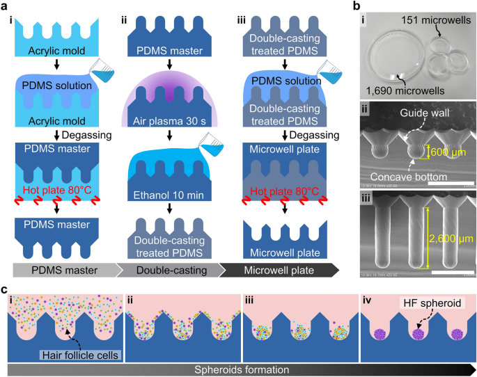
Fabrication of the microwell plate and spheroid formation. (a) Casting method of the PDMS microwell plate. (i) The PDMS master was cast using an acrylic microwell mold. (ii) The PDMS master was then treated by the double-casting process consisting of ethanol and air plasma treatments. (iii) Using the double-casting treated PDMS master, the microwell plate was cast. (b) Images of the microwell plate. (i) The microwell plate was customized at two scales, with 1690 microwell array in 72.4 mm diameter area and 151 microwell array in 20.8 mm diameter area having (ii) 600 μm and (iii) 2600 μm depths, respectively. Scale bars are 2 mm. (c) Process of spheroid formation in the microwell array. (i) Loading of the HF cell suspension on the microwell array. (ii) Sedimentation of the cells by gravity and guidance by the entrance slope. (iii) Aggregation of the cells at the center of the concave-shaped bottom. (iv) HF spheroid formation in the microwells.
Ethical approval
The animal experiments were conducted with ethical approval obtained from the Institutional Animal Care and Use Committee (IACUC) at Sejong University (SJ-20190702), and all protocols related to animal experiments were approved by the IACUC. All experimental procedures were conducted in accordance with the ARRIVE guidelines.
HF cell preparation
The HFCs used in this study were isolated from plucked HFs obtained from the dorsal skin of 6-week-old mice. First, the mice were cervical dislocated, and 70% alcohol was used to disinfect the back. After disinfection, the dorsal skin (1 cm below the neck to 1 cm above the tail, 2 cm to the left and right sides) was harvested using disposable forceps and scissors before placing in a 10 cm Petri dish containing phosphate-buffered saline (PBS). The skin tissue was cut to a size of 1 × 1 cm and rinsed 2–3 times in 10 cm Petri dish containing PBS while replacing the dish. The well-rinsed skin tissue was then submerged in a mixture of DMEM:F12 (1:1) at a concentration of 2.5 mg/ml Dispase II (D4693, Sigma-Aldrich, St. Louis, MO, USA) (approximately 30 ml) at 4 °C. After overnight treatment, the skin tissue was rinsed with PBS. The HFs were pulled out using forceps and put in DMEM:F12 medium in 60 mm Petri dish. To dissociate the HFCs from HF, the hairs were treated with 10 ml of 0.25% trypsin in a 37 °C water bath. After 5 min, trypsin inactivation was carried out by adding 1 ml of fetal bovine serum (FBS). Then, in a 50 ml tube, the HFs were rinsed with HF culture medium (compositions are listed in supplementary table S1)17, and the hair shafts were filtered using a 40 μm mesh strainer. The filtering process was repeated, and the HFCs were resuspended in 1 ml of HF culture medium. The cells were cultured in an incubator with 95% humidity and 5% CO2 at 36.5 °C; the HF culture medium was used and replaced every 2 days. The major population of established cells consist of Cd34 and Cd49f. (supplementary figure S2).
HF spheroid formation
The microwell plates were sterilized using an autoclave (BF-60AC, BioFree CO. LTD, Seoul, Republic of Korea) at 121 ℃ for 15 min. To prevent cell attachment, the microwell plates were precoated by immersion in 4% Pluronic F-127 solution (P2443, Sigma-Aldrich); during this process, air bubbles trapped in the microwells were removed through manual pipetting. After overnight treatment, the Pluronic F-127 solution was washed out twice with D-PBS (Gibco®, Thermo Fisher Scientific, Waltham, MA, USA). Before cell loading, the culture medium was poured onto the microwell plate, and the air bubbles trapped in the microwells were blown out by manual pipetting. The cell suspension was prepared to contain approximately 3 × 10³ cells in each microwell. The cell suspension was then poured on the microwell plates containing the culture medium (Fig. 2c, i). The cells sank into the microwells by gravity and slid down the slope of the guide wall without cell loss (Fig. 2c, ii). The concave shape of the microwell enabled gathering the cells passively at the center of the bottom (Fig. 2c, iii). One day after cell seeding, the HFCs were aggregated and formed spheroids (Fig. 2c, iv). In the microwell array, the culture media was changed in the 2–3 days. The supplied culture media was filled in the reservoir on the microwell array, and the fresh culture media diffused inside the microwells (supplementary figure S3).
Bright-field image measurement
The HF spheroids were cultured in microwells and observed using a microscope (CKX41, Olympus, Tokyo, Japan). Using ImageJ 1.53 k (National Institute of Health, Bethesda, MD, US) image processing software, the spheroid outlines were traced manually, and the size and center positions of the spheroids were measured.
Cell viability analysis
The viability tests of the HF spheroids cultured in the shallow-well and deep-well were analyzed using a LIVE/DEAD® Viability/Cytotoxicity Kit for mammalian cells (Thermo Fisher Scientific). The assay solution contained 0.5 μl of calcein acetoxymethyl ester (calcein AM) solution and 2 μl of ethidium homodimer-1 solution per 1 ml of culture media. The HF spheroids were treated in this solution at room temperature. After 30 min, the HF spheroids were observed using a confocal laser scanning microscope (LSM710, Carl Zeiss, Oberkochen, Germany).
RNA isolation, cDNA synthesis, and RT-qPCR
RNA of 5 × 10⁶ cells of the HFCs and HF spheroids were extracted with TRIzol™ Reagent (Invitrogen, Thermo Fisher Scientific) according to manufacturer instructions. For reverse transcription, M-MLV Reverse Transcriptase (Invitrogen) was used. Real-time quantitative polymerase chain reaction (RT-qPCR) analysis was performed using the CFX Connect™ Real-Time PCR Detection System (BIO-RAD) with SYBR green real-time PCR master Mix (QPK-201, TOYOBO). PCR was performed by denaturation at 94 °C for 3 min, followed by 40 cycles of annealing at 95 °C for 1 min, 60 °C for 1 min, and 72 °C for 1 min; then, a final extension was performed at 72 °C for 5 min. The primer sequences are shown in supplementary table S2. The expression levels were normalized to those of endogenous Gapdh, and the data were analyzed using the delta-delta Ct method.
Immunocytochemistry of HF spheroids
3D-cultured HFCs were fixed with 4% paraformaldehyde overnight at 4 °C. After washing with PBS, the HF spheroids were embedded with FSC22 frozen section media (3,801,480, Leica Biosystems, Wetzlar, Germany). Cryofixed molds were cut into 10–20 µm thickness using a microtome (HM525, Thermo Fisher Scientific). After attachment to silane-coated slide glass (5116-20F, Muto Pure Chemicals, Tokyo, Japan), the samples were fixed with 4% paraformaldehyde, washed with PBS, and stored at − 80 °C.
For immunocytochemistry, HFCs were placed on 12 mm round cover glass in a 12-well culture and fixed with 4% paraformaldehyde. Then, treatment was performed with 1% sodium dodecyl sulfate (SDS) in PBS for 1 min for antigen retrieval. After blocking with 3% horse serum in 0.1% PBST for 1 h, the samples were incubated with primary antibodies overnight at 4 °C. The cells were washed with 0.1% PBST 3 times. The secondary antibodies were used in a 1:500 dilution factor for 1 h. After washing with 0.1% PBST thrice, the secondary antibodies were treated at room temperature for 1 h. After washing, 0.1% Hoechst was applied as treatment for 3 min. The slides were subsequently mounted on a fluorescence mounting medium (Vectashield, Vector Laboratories, Newark, CA, US).
Fluid dynamics analysis in microwell
Computational simulations were conducted to investigate the flow phenomena around the spheroid according to microwell depth using the commercial CFD tool ANSYS Fluent 19.2 (ANSYS, Inc., Canonsburg, PA, US). To simplify calculations for the entire microwell array, a single microwell including a single spheroid was adopted as the 3D computational geometry (Fig. 3). The flow dynamic environment of the conventional culture dish was compared with that of the microwell, and the spheroid diameter was assumed to be 300 μm (Fig. 3a, i). The computational geometries were constructed with depths of 600 μm for the shallow microwell and 2600 μm for the deep microwell, respectively (Fig. 3a, ii and iii). The hexahedral grid was constructed with 162,000 elements for the shallow microwell, and the same grid density was applied to the culture dish and deep microwell model (Fig. 3b). The grid density was determined by the grid independence test with 48,600- and 385,200-element grid models of the shallow microwell geometry (supplementary figure S4). In the microwell array, each spheroid is influenced by biomolecules, such as nutrients, cellular biomolecules, and waste products, and their diffusions contribute to the interactions with neighboring spheroids (Fig. 2c, i). In addition, during the cell culture experiments, operational handling and pipetting generate convective flows inevitably, and the spheroids in the microwell are exposed to this flow directly (Fig. 2c, ii). To predict the effects of biomolecular diffusion and convective flow, the boundary conditions were set for each phenomenon (Fig. 2d). In the diffusion simulation model, the periodic condition was applied to each of the opposite sides to consider the effects of spheroids in the six neighboring microwells (Fig. 2d, i). The species transport model was applied to assume diffusion of the biomolecules from the spheroid with 50% mass fraction, and the diffusion coefficient was 10–10 m2/s18. The species transport model predicts the mass fraction without source and chemical reactions using the following conservation equation (Eq. 1), and for laminar flow, the diffusion flux is determined based on Fick’s law without thermal diffusion (Eq. 2)19.
$$frac{partial }{partial t}left(rho {Y}_{i}right)+nabla cdot left(rho overrightarrow{v}{Y}_{i}right)=nabla cdot {overrightarrow{J}}_{i}$$
(1)
$${overrightarrow{J}}_{i}=-rho {D}_{i,m}nabla {Y}_{i}$$
(2)
where ρ is the fluid density, Yi is the local mass fraction of each species, (overrightarrow{v}) is the velocity component, ({overrightarrow{J}}_{i}) is the diffusion flux of each species, and Di,m is the mass diffusion coefficient of species i. The culture medium was assumed as a homogeneous and incompressible Newtonian fluid, i.e., water of 998.2 kg m−3 density10. To observe the diffusion process, transient simulations were performed, and the timestep was set to 10 s, with each timestep being calculated for 500 iterations. The convective flow analysis considered the pipetting flow generated during the cell culture process. The flow direction was assumed to be perpendicular to the microwell, and a mass flow rate of 1 ml/s was set for the top of the geometry (Fig. 2d, ii). The pressure outlet condition (1 atm) was applied to the boundary with adjacent microwells. Laminar flow was simulated at steady state following the governing equations of continuity (Eq. 3) and momentum (Eq. 4)19.
$$frac{partial rho }{partial t}+nabla cdot left(rho overrightarrow{v}right)={S}_{m}$$
(3)
$$frac{partial (rho overrightarrow{v})}{partial t}+nabla cdot left(rho overrightarrow{v}overrightarrow{v}right)=-nabla rho +nabla cdot left(tau right)+rho g+F$$
(4)
where Sm is the mass added from source, τ is the stress component, g is the gravitational acceleration, and F is the force component. Each case was calculated for 10,000 iterations, and the residuals of all cases were less than 1 × 10⁻⁶.
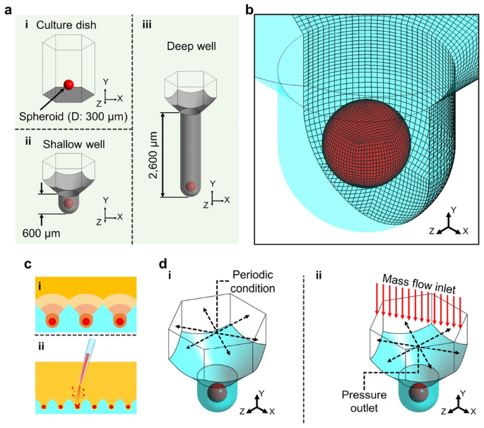
Computational models and conditions. (a) Computational geometries of the (i) culture dish, (ii) shallow well, and (iii) deep well. (b) Computational grid system. (c) Phenomena of exposing the spheroids in the microwell array. (i) Diffusion of biomolecules secreted from the spheroids. (ii) Convective flow generated during spheroid culture. (d) Simulated boundary conditions for the (i) diffusion of biomolecules and (ii) convective flow in the microwell.
- SEO Powered Content & PR Distribution. Get Amplified Today.
- PlatoData.Network Vertical Generative Ai. Empower Yourself. Access Here.
- PlatoAiStream. Web3 Intelligence. Knowledge Amplified. Access Here.
- PlatoESG. Carbon, CleanTech, Energy, Environment, Solar, Waste Management. Access Here.
- PlatoHealth. Biotech and Clinical Trials Intelligence. Access Here.
- Source: https://www.nature.com/articles/s41598-023-49510-6